
Improving the mechanized logging safety on steep slopes through the analysis of dynamic behavior of harvester rope anchor systems
iForest - Biogeosciences and Forestry, Volume 19, Issue 4, Pages 283-291 (2026)
doi: https://doi.org/10.3832/ifor4983-019
Published: Jul 28, 2026 - Copyright © 2026 SISEF
Research Articles
Abstract
Mechanized logging on steep slopes using forestry machines equipped with winch-rope anchor systems to ensure equipment stability and safe operation is becoming increasingly popular. The parameters that characterize the dynamic behavior of both the harvester and the rope anchor system are crucial to the operational efficiency of the anchor system. The purpose of this study is to create a comprehensive mathematical 12-mass model for the dynamic system “harvester - manipulator - anchor system - natural anchor - log - soil”. The developed model combines all the key components of the system and enables assessment of their mutual influence on the quantitative parameters of the dynamic processes occurring in the system. The model includes 34 generalized coordinates that describe the displacement of the center of mass of each component of the harvester during its operations for felling trees and moving logs to the laying place. To construct a system of equations of motion characterizing the dynamics of the simulated system, an approach based on Lagrange equations of the 2nd kind was used. The model allows for analyzing the influence of the harvester’s design and operating parameters, and of the physical and mechanical properties of the ground, on the harvester load with a manipulator and on the structural elements of the anchor system. To demonstrate the model’s functionality, a specific 6-wheeled harvester weighing 20 tons was chosen as the study object while operating on slopes with a steepness ranging from 50% to 100%. The variable inertial loads on the manipulator from the displaced log cause oscillations in the tensile force of the anchor rope. The maximum values of the force in the studied range of slope steepness increased from 19 kN to 72 kN, while the average values increased from 16 kN to 65 kN, with an increase of oscillation in the range 6-14 kN. The oscillation frequency remains constant throughout the log’s motion, as it is determined by the geometric dimensions of the structural elements in the simulated dynamic system.
Keywords
Oscillatory Processes, Modeling, Lagrange Equation, Dynamic Parameters, Dynamic Rope Tensile Force, Anchor Tree
Introduction
Natural forests suitable for logging are often found in challenging mountainous areas, with high-quality stands typically located on steep slopes ([45], [8]), making logging difficult ([1]). However, mechanized logging is currently being carried out in steep slope territories across several European countries (Italy, Croatia, Czech Republic, etc.), as well as in America (USA, Canada, Chile, etc.), Asia (Turkey, China, Korea, etc.), Australia, and New Zealand ([4], [33], [1]). Logging operations are only permitted in areas where the ground’s slope is within the safe limits for operating logging machines. This maximum slope is defined by safety regulations for mechanized logging in various countries ([3], [45]). For example, current regulations in the province of British Columbia (Canada) restrict the safe use of land-based logging equipment on slopes not exceeding 40% (nearly 22 degrees - [29]). Thus, the expansion of the possibilities for mechanized logging on steep slopes is directly related to improvements in the technical capabilities of forestry machines, which can increase the maximum inclination angles for safe operation.
Several approaches to solving this problem are known, for example, by optimizing the kinematic schemes of harvester manipulators ([21]) or introducing digital technologies based on artificial intelligence to optimize logging planning and execution within a cyber-physical system in accordance with the Forestry 4.0 concept ([15]). However, a promising approach is to incorporate additional technical devices into the harvester design to expand the capabilities of modern forestry machines for safe operation on steep slopes.
One of the effective measures to prevent harvesters from rolling down the slope under their own weight is the use of rope anchor systems based on a traction winch mounted on the supporting frame of a forestry machine ([45], [33]). Currently, both specialized harvesters with an initially installed winch and winch equipment kits are used to modify existing harvesters ([12]). Using a rope winch allows forestry machines to be operated safely on steep support surfaces with slopes ranging from 60% to 100% (approximately 30 to 45 degrees - [3]). These slopes greatly exceed the maximum incline allowed by safety regulations for the safe operation of forestry equipment without an anchor-rope winch. A theoretical assessment of the stability of forestry machines equipped with a winch anchoring system on steep slopes was conducted by Sessions et al. ([38]). The developed mathematical model enables assessment of the impact of equipment size and technical characteristics, soil properties, and site conditions on acceptable slopes and ground pressure.
Nowadays, rope anchor systems based on a traction winch can be dynamic or static ([22], [13]). In dynamic anchor systems, a winch is attached to heavy mobile equipment, such as a bulldozer, tractor, or excavator, which acts as an artificial anchor and synchronizes the winch’s operation with the harvester movement. In contrast, in static anchor systems, the winch is attached to the harvester frame, and a tree or stump at the top of the slope serves as a natural retaining anchor due to its strength and resistance to uprooting ([10]). The results of experimental studies on the selection of such an anchor tree have been presented in Marchi et al. ([25]). Lyons et al. ([23]) explored the use of three stumps as an anchoring option to increase the bearing capacity of a natural anchor, in case one stump alone is not sufficient.
The positive impact of rope anchor systems based on a retaining winch is evident not only in their ability to facilitate mechanized logging on extremely steep slopes, but also in various other operations. Kormanek et al. ([17]), Machuga et al. ([24]), and Belart et al. ([2]) reported that rope anchoring for forest machinery also has a positive effect on soil and groundwater, due to a more favorable pressure distribution and reduced soil compaction. Moreover, the use of a retaining winch increases logging productivity on moderately steep slopes. However, on a very steep slope, an increase in the maximum load weight from using a winch does not offset the reduction in machine speed ([46]). An increase in the reliability of these forest machines has also been reported ([18]).
According to Di Fulvio et al. ([7]), the further expansion of efficient and safe mechanized logging requires adapting forestry equipment to more severe operating conditions in areas with large permissible inclination angles of the support surface. This necessitates conducting a range of theoretical and practical studies to develop new systems, machines, and mechanisms capable of addressing this challenge ([47], [26]).
Research on logging machines with rope anchor systems using retaining winches on steep slopes is primarily experimental, focusing on field observations of the static and dynamic behaviors of parameters related to harvester operation and their anchoring systems. For example, Holzleitner et al. ([14]) developed an automated system to monitor tensile forces in anchor ropes, enabling measurements at various stages of harvester and forwarder operation. Similar studies conducted by Mologni et al. ([29]) on large forwarders moving along a slope showed higher tensile force in the anchor rope when moving upwards. Also, Mologni et al. ([30], [31]) considered dynamic anchoring systems in which a tracked excavator serves as a mobile anchor, showing higher tensile force values for the anchoring machine.
A comparative analysis of the results from the aforementioned studies reveals qualitative agreement. However, quantitative comparisons are infeasible due to significant differences in experimental conditions and insufficient details. Across all studies, there is significant variability in the tensile force of anchor ropes during forestry machinery operation, influenced by factors such as the operating stage and mode, the direction of machine movement, soil inclination angle, distance to the anchor, and other variables.
Understanding how the work processes affect the anchor system of a working harvester is essential in theoretical studies of the harvester’s dynamic behavior, and ultimately to determine the safety of logging on steep slopes. Modern mathematical modeling methods, combined with high-performance computers, enable the creation of complex dynamic models of work processes that account for numerous significant quantitative parameters contributing to their formation, and the analysis of the degree and direction of their individual and combined influence.
To date, the dynamic behavior of a working harvester on a steep slope has been modeled using multi-mass models constructed using the Dalembert principle or Lagrange equations of the second kind. These models differ in the number of structural components of the harvester’s design they account for, and in their approaches to accounting for the influence of the anchor rope. These models offer varying degrees of detail of the dynamic processes being studied. For example, Grigorev et al. ([11]) considered multi-mass models of wheeled machines and skidding tractors operating on a slope that simulated machine vibrations in both longitudinal and transverse planes. Sessions et al. ([38]) developed a multi-mass model of a tracked tractor to study the machine’s traction capacity and the maximum permitted inclination angles. This is similar to the models developed by Papadopoulos & Sarkar ([34]) and Naillon & Rappin ([33]). The influence of the anchor rope was modeled using a stationary force. This approach did not account for oscillations in the anchor rope’s tension, which could affect the machine’s dynamic behavior. However, the need to consider these oscillations was demonstrated during experimental studies of harvesters in field conditions ([14]). Sun et al. ([41]) proposed a mathematical model to study the dynamics of forest machines operating on slopes. The design of these machines includes special articulated mechanisms for leveling. Ismoilov et al. ([16]), using the MSC/ADAMS software package, analyzed the dynamics of a wheeled, four-axle, articulated forwarder moving along a slope. Mergl & Kašpárek ([27]) used the aforementioned software package to evaluate the effect of a manipulator on a forestry machine operating on slopes without an anchor rope. However, at present, no dynamic models are available to enable the quick assessment of rope tension for the development of control systems and the prevention of accidents ([44]).
The aim of this study is to create a comprehensive 12-mass mathematical model for the dynamic system “harvester - manipulator - anchor system - natural anchor -log - soil”. The model developed combines all the key components of the system under study and enables assessing their mutual influence on the quantitative parameters of the dynamic processes occurring in the system. The basic principle for constructing a dynamic model was to represent a working harvester on a steep slope as a single object supported by a static rope anchor system, accounting for the individual characteristics of its structural components and the complex interactions among them.
Materials and methods
Dynamic mathematical model
The dynamic state of a harvester on a steep slope, anchored by a rope system to prevent uncontrolled movement, results from the interaction among several structural components. These components include the harvester itself, which is a self-propelled machine with equipment mounted on it, a manipulator mounted on the harvester’s frame, an anchor system consisting of an anchor winch and an anchor rope, a movable log, and the natural anchor, which can be located on a tree or stump in the cutting area. The soil of the supporting surface also plays a role in this process. Considering the geometric and physical-mechanical characteristics of each component, as well as the varying nature of the load during moving logs from the cutting site to the temporary stacking site, we can perform a detailed analysis of the dynamic load on the harvester and its anchor system during operation.
Fig. 1 shows a dynamic mathematical model of the “harvester - manipulator - anchor system - natural anchor - log - soil” system, which implements this paradigm for a three-axle wheeled harvester with an uncut machine frame, using a suitable anchor tree as the natural anchor. The model allows for simulating the dynamics of a motionless harvester fixed on a slope using a single-branch anchor rope and moving logs from the cutting site to the temporary stacking site using a manipulator. Fig. S1 (in Supplementary material) shows a geometric model of the “harvester - manipulator - anchor system - natural anchor - log - soil” system corresponding to the model in Fig. 1.
Fig. 1 - A dynamic mathematical model.
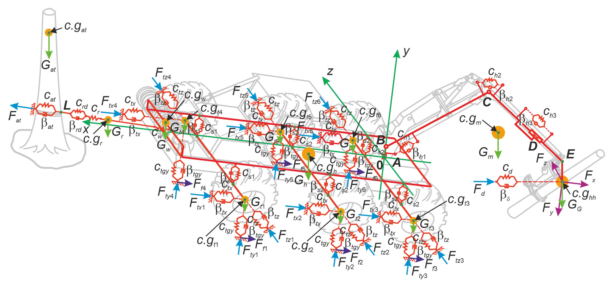
When constructing a dynamic mathematical model, the following considerations were taken into account for its structural components. The metal structures of the harvester’s frame have a length Lf and a width Df. The frame consists of rigid rods characterized by linear weights gf and the inertia moments of the sections EFf. The total mass of the harvester Mh is the sum of the masses of its main structural elements, i.e., frame, cabin, power plant, auxiliary equipment, wheel axle suspensions, and wheels. The center of mass of the harvester is located at point c.gh.
The manipulator provides the necessary movement of the harvester head and logs within the harvester’s working area and has four degrees of freedom. Accordingly, it has four movable links, including a rotary column (link 1), a rotary boom (link 2), a rotary handle (link 3), and a translational telescopic link (link 4). These links are considered elastic rods with length Li and a variable cross-sectional area along their length. They are characterized by their linear weights gi and moments of inertia for bending in the vertical and transverse directions, denoted by EJiν and EJic. The movements of the links in the manipulator are driven by hydraulic cylinders, with each cylinder moving one link. Based on the practice of dynamic analysis of multi-link manipulators ([6], [19], [40]), the drive hydraulic cylinders can be considered as viscoelastic elements. Thus, the characteristics of the i-th hydraulic cylinder are described by the stiffness coefficient chi and the viscous resistance coefficient βhi ([19]). The total mass of the manipulator Mm is the sum of the masses of all links and hydraulic cylinders. The center of mass of the manipulator is located at point c.gm.
The metal structure of the anchor winch, including the drum, is considered as a set of interconnected elastic rods. It is characterized by the total weight Mw of the winch itself and the part of the anchor rope F that is wound around the drum, as well as the coefficient of stiffness in the longitudinal direction cw. The center of mass of the anchor winch is located at point c.gw.
The wheel axles of the harvester are considered as rigid rods that are connected to the frame by the same type of suspensions. In the vertical direction, the dynamic characteristics of suspensions are expressed by the stiffness coefficient cs and viscous resistance coefficient βs. Harvester wheels are considered as viscoelastic elements with a mass Mt. The center of mass of the i-th wheel is located at point c.gti. In accordance with the practice of analyzing the interaction of wheels of self-propelled multiaxial chassis with the support surface ([39], [36]), their dynamic characteristics are expressed by the stiffness coefficients of the tire material in the longitudinal (ctx), radial (cty), and transverse (ctz) directions of tire deformation, as well as the viscous resistance coefficients of the tire material in the specified directions βtx, βty, and βtz.
The anchor rope is considered a flexible thread with constant cross-section, diameter dr, linear weight gr, and stiffness coefficient cr. The rope has a variable length depending on the distance from the anchor tree Lr ∈ [Lr, min; Lr, max] and, accordingly, a variable mass Mr. In the span between the anchor tree and the anchor winch, the rope has a natural static sag, the magnitude of which depends on the tensile force ([20]). The center of mass of the anchor rope is located at point c.gr.
The anchor tree is considered an elastic cantilever rod of variable cross-section with height Lat. The density ρat expresses its characteristics, the stiffness coefficient cat and the viscous resistance coefficient βat of wood ([35]). The mass of the anchor tree Mat is concentrated in the center of mass c.gat at a height Hat above the ground.
The soil of the support surface is considered as a viscoelastic medium. Its physical and mechanical properties depend on the type and condition of the soil. These properties are expressed by the coefficients of stiffness (cgr) and viscous resistance (βgr) in the vertical direction ([11], [42]), as well as by the harvester’s wheel slip, μgr ([24], [5]). The dynamic model uses the kinetic coefficient of sliding, as when the harvester is running, there is constant, oscillating sliding of the braked wheels along the supporting surface, in accordance with a constant, oscillating change in the length of the anchor rope. In this dynamic model, the effects of soil compaction are not considered.
The Kelvin-Voigt model was used for all structural components as their viscoelastic representation ([28]).
The system of motion equations
To construct a system of motion equations that characterize the dynamics of the six-component simulated system, an approach based on the Lagrange equations of the 2nd kind ([43]) was used. The model is characterized by a total of 34 degrees of freedom and corresponding 34 generalized coordinates. These generalized coordinates are shown in Fig. S2 (Supplementary material) and represent linear and angular displacements of the center of mass of each component in the simulated system. These coordinates will be used in further calculations to determine the positions of the components.
In relation to the dynamic model under consideration, the system of Lagrange equations of the 2nd kind is expressed as (eqn. 1):
where T is the total kinetic energy of the simulated system, qi is the i-th generalized coordinate, {dot}qi is the i-th generalized velocity, Qi is the i-th generalized force.
The total kinetic energy T is the sum of the individual contributions of the kinetic energy of the simulated system’s individual components: harvester (Th), manipulator (Tm), harvester head together with the log (TG), wheels (Tt), anchor winch (Tw), anchor rope (Tr), and anchor tree (Tat). It is expressed by eqn. 2:
where Jhx, Jhy, Jhz are the harvester inertia moments when rotating relative to the coordinate axes x, y, z, and MG, JGz are the mass of the harvester head together with the log and the inertia moment when swinging relative to the coordinate axis z.
To determine the generalized forces Qi corresponding to the generalized coordinates qi, the algorithm described in Molotnikov & Molotnikova ([32]) was used. This algorithm accounts for the effects of various forces used in the dynamic model of a six-component system. These forces include gravity, elasticity of system elements, resistance to sliding of wheels on the ground, and viscous resistance during deformation of system elements.
For each generalized force Qi, the work sum δA of all forces taken into account in the geometric model of the system was determined on the generalized possible displacement δqi, provided that 0 (zero) of the remaining generalized possible displacements are equal (eqn. 3):
where i = [h, m, G, w, r, at], j = [x, y, Z, r, w, d, at], k = [1, 2, …, 6]; Fr is elastic tensile force of the anchor rope, Fw is elastic bending force of the anchor winch metal structure, Fx, Fy, Fz are projections on coordinate axes x, y and z operational forces during harvester operation, Fd is viscoelastic force of the harvester head damper to reduce its rocking, Fat is viscoelastic force when bending an anchor tree, Ftxk, Ftyk, Ftzk are viscoelastic forces during deformation of the k-th harvester wheel along the coordinate axes x, y and z, and Fsk is viscoelastic force generated by the k-th wheel suspension.
Applying eqn. 3 sequentially for all generalized possible displacements δqi, we obtain the following calculation equations in matrix form to determine the generalized forces Qi (1 ≤ i ≤ 34 - eqn. 4):
where {Q}, {q}, dot{q} are vectors of generalized forces, generalized coordinates, and generalized velocities, {F} is vector of projections of operational forces on the coordinate axes, {D} is vector of constant coefficients, [A] is diagonal matrix of coefficients for generalized coordinates, [B] is the square matrix of coefficients at generalized velocities, [C] is rectangular matrix for projections of operational forces. The structure and calculation formulas for the elements of these vectors and matrices are given in Appendix 1 (Supplementary material).
Substituting eqn. 2 and eqn. 4 into eqn. 1 yields the final form of the system of motion equations characterizing the dynamics of the simulated six-component system (eqn. 5):
under initial conditions (at τ = τ0 = 0 - eqn. 6, eqn. 7):
where dot{q} is a vector of generalized accelerations, [E] is a diagonal matrix of coefficients for generalized accelerations, and {G} is a vector of the right-hand sides of the motion equations. The structure and calculation formulas for the elements of the vectors {q̈} and {G}, and the matrix [E], are given in the Supplementary Material.
Force impact on a working harvester
The force impact on the harvester during operation is not only caused by the action of weights created by the structural components of the six-component simulated system. Inertial forces that arise when the log is moved from where it was cut to where it will be stacked also play a significant role. Conditionally, they can be considered to be applied at the center of mass c.ghh (Fig. 1). These loads form a vector of projections of operational forces on the coordinate axes {F} in eqn. 4 when calculating the elements of the vector of generalized forces {Q}. Thus, the vector {F} is defined as (eqn. 8):
with i = j = [1, 2, 3]. The modulus of operational forces is determined as (eqn. 9):
where g is acceleration of gravity, qm1 is the angle of rotation of the manipulator column (link 1), Fc,ix, Fc,iy, Fc,iz are projections on x, y and z the axes of inertial centrifugal force during rotation of the i-th manipulator rotary link, Fτ,ix, Fτ,iy, Fτ,iz are projections on x, y and z the axes of inertial tangential force during rotation of the i-th manipulator rotary link, F4x, F4y, F4z are projections on x, y and z the axes of inertial force during linear movement of the manipulator telescopic link, Fj4x is the Coriolis force at the simultaneous movement of the j-th rotary link and telescopic link.
The direction and magnitude of the inertial forces are determined by the time variation laws of the kinematic parameters of the manipulator’s links when moving the log. The mathematical model of the six-component system under study takes into account that, when moving the log with a motionless harvester, both joint and individual operation of the movement mechanisms of the manipulator links is possible. The model assumes that the law of change in the coordinate of the k-th motion in time qmk(τ) obeys the piecewise linear law of change in the motion velocity dot{q}mk(τ) with three characteristic periods: (i) the overclocking period from rest to stationary speed (dot{q}mk = qst,k = const); (ii) the period of steady motion with stationary speed (dot{q}st,k); (iii) the braking period to a complete stop.
Solving a system of motion equations
The Runge-Kutta method of the 4th order ([37]) was used to solve a system of ordinary differential equations of the 2nd order (eqn. 5) under initial conditions (eqn. 6, eqn. 7). The initial system of 34 ordinary differential equations of the 2nd order of the form eqn. 5, using the notation ri = q̇i, is reduced to a system of 68 ordinary differential equations of the 1st order (eqn. 10):
under initial conditions (eqn. 6, eqn. 11):
The solution of the equation system (eqn. 5) also serves as the basis for modeling the dynamic loading of the anchor system and evaluating the safety of its operation. These characteristics, at an arbitrary time τ, quantify parameters such as the dynamic tensile force of the anchor rope Sr(τ), the dynamic tensile stress of the anchor rope σr(τ), the strength margin factor of the anchor rope in terms of breaking force nr(τ) and the margin factor in terms of overturning (uprooting) force on the anchor tree nat(τ). They are calculated as follows (eqn. 12, eqn. 13, eqn. 14, eqn. 15):
where Sr0 is the pre-tensioning force of the anchor rope (at the initial moment of time τ0), εat is the relative displacement of the longitudinal axis of the anchor tree, in the section where the anchor rope attaches to it, fr, [Tr] are the total cross-sectional area of the wires and the breaking force of the anchor rope ([9]), Fat(dtr, Htr) is the critical overturning (uprooting) force of an anchor tree depending on its diameter dtr, height Htr and soil condition, ψL is the inclination angle of the anchor rope longitudinal axis to the coordinate axis x at the point L of its attachment to the anchor tree ([20]).
Results
The mathematical model of the six-component system was implemented in the computer program “Dynamics of a harvester with an anchor rope for logging on a steep slope”.
To analyze the influence of the main technical characteristics of the harvester and anchor system on the dynamic parameters of the “harvester - manipulator - anchor system - natural anchor - log - soil” system, we chose a variant of a 6-wheel harvester with an uncut frame. The main technical characteristics of the simulated harvester are shown in Tab. 1.
Tab. 1 - The main technical characteristics of the simulated harvester.
| Technical characteristics | Designation | Value |
|---|---|---|
| Harvester total mass (kg) | M h | 20.000 |
| Length/width of the harvester frame (m) | Lf/ Df | 7.8/2.0 |
| Harvester track width (m) | D h | 2.6 |
| Installation dimensions of the harvester axes (m) | xt1 / xt2 / xt3 | 3.8/1.9/-0.9 |
| Manipulator mass (kg) | M m | 2100 |
| Length of the manipulator links (m) | L1/L2/L3/L4 | 1.0/4.9/3.4/1.4 |
| Harvester head mass (kg) | M hh | 1 500 |
| Distance from the harvester to the anchor tree (m) | L r | 30 |
| Anchor rope diameter (mm) | d r | 15 |
| Breaking force of the anchor rope (kN) | T r | 137 |
| Preliminary tensile force of the anchor rope (kN) | S r0 | 10 |
| Height/diameter of the anchor tree (m) | Hat/Dat | 26/0.4 |
| Log length (m) | l tr | 6 |
| Density of the log wood (kg m-3) | ρ tr | 400 |
| Inclination angle of the ground surface (deg) | α s | 30 |
| Wheel slip | μ gr | 0.4 |
The calculated manipulator motion was assumed to consist of individual link movements, simulating the process of moving a log from the cutting site to the temporary stacking site. The cutting site is located along the longitudinal axis of the harvester, which corresponds to the x-axis. The stacking site is located along the transverse axis, which corresponds to the z-axis. The movements are performed in the following order: (i) lifting the boom (link 2) from the initial lower position; (ii) turning the column (link 1) from the initial longitudinal position; (iii) extending the telescopic link (link 4) from the initial maximum pushed position; (iv) lowering the handle (link 3) from the initial upper position.
The parameters of each link’s movement during the process of moving the log are presented in Tab. 2.
Tab. 2 - The parameters of the movement of the manipulator links when moving the log. The asterisk (*) indicates the unit of measurement for the parameter of the telescopic link (link 4).
| Parameter | Parameter value | |||
|---|---|---|---|---|
| link 1 | link 2 | link 3 | link 4 | |
| Time of the start/end of the movement (s) | 1.0/7.0 | 0 /3.8 | 3.0 /7.3 | 2.0 /8.0 |
| Coordinate of the link at the initial/final moment (degree) or (m)* | 0 /90 | 10 /40 | 60 /0 | 0 /1.0 |
| Steady motion speed (deg s-1) or (m s-1)* | 40 | 10 | 20 | 0.2 |
| Acceleration during overclocking/braking (deg s-2) or (m s-2)* | 10 /-10 | 10 /-20 | 15 /-15 | 0.2 /-0.2 |
| Overclocking/braking time (s) | 3.0/3.0 | 1.0 /0.5 | 1.3 /1.3 | 1.0 /1.0 |
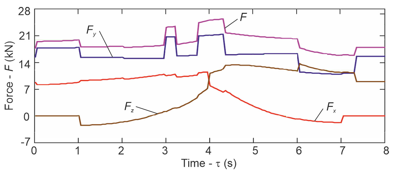
Fig. 2 shows the time-dependent graphs of the module and the projections of the operational forces onto the coordinate axes as the log is moved. The greatest values of these forces are observed approximately in the time interval between 3.7 and 4.3 seconds, which corresponds to when three links are in motion - rotary links 1 and 3 and telescopic link 4.
Fig. 2 - The time variation of the forces acting on the harvester head.
Tab. 3 presents the quantitative results of dynamic calculations for the harvester’s basic option and its anchor system during log movement. These results characterize the ranges of oscillations in the main dynamic parameters. Fig. S3 to Fig. S5 (Supplementary material) illustrate the dynamics of these key parameters. As the time step used for integrating the system of differential equations (eqn. 5) was 0.1 milliseconds, these figures present the calculated results for four time intervals of 0.05 seconds each: (i) the initial period of the manipulator operation is from 0.50 to 0.55 seconds, when only the boom (link 2) performs the rotary movement; (ii) the period from 3.20 to 3.25 seconds, when all four links of the manipulator move together; (iii) the period from 4.1 to 4.15 seconds, in which the maximum operational load on the harvester head is observed and three links are moving together, i.e., the column (link 1), the handle (link 3), and the telescopic link (link 4); (iv) the final period of the manipulator operation is from 7.50 to 7.55 seconds, when only the telescopic link (link 4) performs the movement.
Tab. 3 - Ranges of oscillation of main dynamic parameters of the simulated harvester.
| Parameter | Minimum | Maximum |
|---|---|---|
| Movement of the center of mass of harvester along the x axis (mm) | -0.9 | 0.5 |
| Movement of the center of mass of harvester along the y axis (mm) | -15.3 | 0.0 |
| Movement of the center of mass of harvester along the z axis (mm) | -35.3 | -0.4 |
| Turning of the harvester around the z axis (degree) | -14.8 | 3.7 |
| Movement of the center of mass of manipulator along the x axis (mm) | -5.5 | 1.8 |
| Movement of the center of mass of manipulator along the y axis (mm) | -10.2 | 32.5 |
| Movement of the center of mass of harvester head along the x axis (mm) | -11.7 | 12.5 |
| Movement of the center of mass of harvester head along the y axis (mm) | -13.7 | 9.5 |
| Movement of the winch shell along the x axis (mm) | -12.5 | 2.4 |
| Movement of the center of mass of anchor tree along the x axis (mm) | -1.9 | 1.7 |
| Tensile force in the anchor rope (kN) | 13.2 | 19.5 |
| Axial tensile stress in the anchor rope (MPa) | 153.2 | 226.1 |
| Strength margin factor of the anchor rope in terms of breaking force | 7.0 | 10.4 |
| Margin factor for the overturning force on the anchor tree | 2.1 | 3.1 |
A quantitative analysis of the graphs in Fig. S3 to Fig. S5 (Supplementary material) showed that the oscillation periods of the studied characteristics are independent of operating loads and do not change during log movement. They are determined by geometric dimensions of structural elements of a simulated dynamic system. The approximate oscillation frequencies of the dynamic characteristics of the anchor rope (Sr, σr, nr, nat) and the displacement of the center of mass of the anchor winch q32 are approximately 1.8 kHz. The oscillation frequency of the center of mass of the harvester head q10 is approximately 5 kHz. The dynamics of the center-of-mass movement of the anchor tree q34 have a distinctive feature. High-frequency vibration at 5.3 kHz and low-frequency vibration at 440 Hz can be clearly observed.
A visual analysis of the dynamic processes in Fig. S3 to Fig. S5 (Supplementary material) revealed that the investigated parameters of the harvester and its anchor system exhibit a variable range during the log moving. The magnitude of this range is defined as the difference between the two adjacent extremes of a given k-th parameter, as shown in eqn. 16:
where Uk,extr,1 and Uk,extr,2 are values of the previous and subsequent extreme points of the dynamic process.
To quantify the magnitude of the oscillations in the parameters of the harvester basic option, histograms were generated to show their distributions over the range between the minimum and maximum values (ΔUk,min and ΔUk,max, respectively). These histograms are presented in Fig. S6 (Supplementary material). A comparison of the histograms for characteristic time intervals with the level of operational load in those same time intervals (Fig. 2) leads to the following conclusion: as the load increases, the ranges of the parameters Sr, σr, nr, and nat also increase, and their values become more consistent and have a narrower spread.
Discussion
In this study, we present, for the first time, an approach to modeling the dynamic behavior of a wheeled harvester with an anchor rope system, using a winch and an anchor tree. This approach is based on a complex mathematical model that includes six components: harvester, manipulator, anchor system, natural anchor, log, and soil. This approach enables combining all the key components of the phenomenon under study into a single model and evaluating their mutual influence on the quantitative parameters of ongoing dynamic processes. Using this model requires specifying a significant amount of source data. These can be roughly divided into groups, such as: (i) structural dimensions, weight, and mechanical properties of the main structural components of the harvester and anchor system; (ii) dimensions and physical properties of anchor trees; (iii) geometric parameters of the slope and physical and mechanical properties of the support surface; (iv) operating parameters during harvester operation, which determine the kinematics of log movement and the time change in the load level of the structural components of the harvester and rope anchor system.
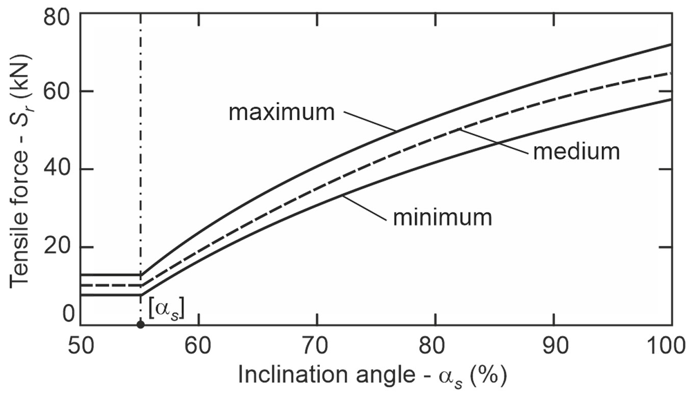
The key characteristic of the dynamic behavior of the harvester’s rope anchor system is the dynamic tensile force of the anchor rope Sr(τ). It is determined by eqn. 12, based on the pre-tensioning force of the anchor rope Sr0 and the elongation of the anchor rope calculated for the moment of time τ. The tensile force of the anchor rope exhibits an oscillatory pattern (Fig. 3), with its amplitude and extreme values increasing as the slope becomes steeper. An analysis of the graphs in Fig. 2leads us to conclude that the main cause of the dynamic behavior of the tensile force in the anchor rope during operations is the time-varying inertial force due to the acceleration of moving logs. For the simulated harvester, the change in the tensile force with increasing slope steepness is shown in Fig. 4. The maximum values of the force in the studied range of slope steepness increased from 19 to 72 kN, while the average values increased from 16 to 65 kN, with an increase in the range of oscillation from 6 to 14 kN.
Fig. 3 - The dynamics of the anchor’s rope tensile force.
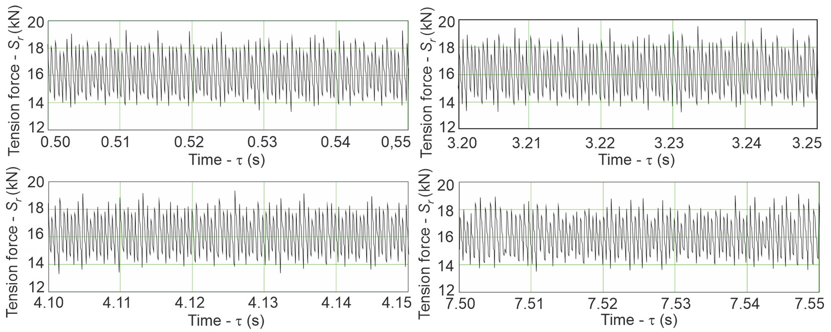
Fig. 4 - Influence of the inclination angle of the support surface on the tensile force of the anchor rope.
Such a change in the tensile force of the anchor rope over time during the operation of forestry machinery is confirmed by well-known field research of various types of harvesters and forwarders in different operating conditions on steep slopes ([14], [29], [30], [31]). The dependence of the support surface inclination angle on the tensile force of the anchor rope is also qualitatively consistent with the findings of the same studies.
An objective quantitative comparison between the modeling results for the anchor rope tensile force and the data from these studies is infeasible due to insufficient information to apply the developed mathematical model. However, given that the simulation was conducted for a real-world harvester, it is possible to make a rough comparison between the real and simulated data. The data presented by Mologni et al. ([31]) are the most suitable for such a comparison. During the work of felling and storing trees using a CAT 552-2 tracked harvester weighing 38 tons on slopes up to 77%, the average tensile forces in the anchor rope ranged from 70 to 77 kN, with maximum values ranging from 130 to 137 kN. Our simulated data (Fig. 4) with the same slope are 52 and 59 kN, respectively.
As shown in Fig. 4, for a slope steepness lower than 55% (< 29 degrees), the tensile force remains constant, although it fluctuates within a range of 4 kN. When the slope steepness exceeds 55%, the tensile force increases. Thus, the breaking point of the Sr(αs) curve defines the threshold for the slope steepness αs. Above this boundary, the mandatory use of a rope anchor system is necessary to ensure the stability and safety of the harvester during tree felling operations. The value αs ≈ 55%, obtained using the developed mathematical model, is consistent with data reported in the literature ([3], [13], [46]). The value αs is mainly influenced by the total weight of the harvester, the slip coefficient of the wheels on the soil, and the pre-tensioning force of the anchor rope. It increases as these characteristics increase. Therefore, it is a value that can change for the same harvester when it operates in different cutting areas with different pre-tensioning of the anchor rope.
As shown by the simulation results, pre-tensioning the anchor rope before the beginning of harvester operations improves the maximum inclination angle of the supporting surface. However, this leads to a non-linear increase in the average and maximum values of the total anchor rope tension. This finding is qualitatively consistent with the results of the research by Visser & Stampfer ([45]).
Other characteristics of interest of the dynamic behavior, such as σr(τ), nr(τ) and nat(τ), are uniquely determined by the force Sr(τ). This is because, according to eqn. 13 and eqn. 14, these characteristics are different from Sr(τ) by a constant factor.
Obviously, the minimum values of the strength margin factor of the anchor rope in terms of breaking force nr,min and the margin factor for the overturning force on the anchor tree nat,min, which are determined by the maximum values of the rope tension Sr,max, determine the conditions for harvester safe operation on the slope. These conditions are expressed by inequalities (eqn. 17, eqn. 18):
where [nr], [nat] are normative margin factors, which are established by technical regulations that ensure the safety of harvester operation.
When harvesters are operating on steep slopes, there is a change in the magnitude of the load acting on the mechanisms of movement of the manipulator’s links during the spatial movement of the log. Experimental studies by Mergl & Kašpárek ([27]) showed that with an increase in the inclination of the manipulator rotary mechanism caused by the location of the harvester on an inclined support surface, more lifting torque is required to manipulate logs of the same weight. This is most evident in the longitudinal plane of the machine when working downhill. Simulated calculations also produce similar results: when the slope increases from 27% to 100% (or from 15 degrees to 45 degrees), the lifting moment increases by approximately 30%.
Conclusions
The dynamic mathematical 12-mass model presented in this study integrates all the key components of the simulated phenomenon into a single, interconnected system. This includes the harvester itself, with a manipulator and harvester head attached, a moving log in space, an anchor system consisting of an anchor rope and winch, and an anchor tree for fastening the anchor rope to the soil of the support surface.
As a result, this dynamic model of the six-component “harvester - manipulator - anchor system - natural anchor - log - soil” system enables mathematical modeling of workflows for a three-axle wheeled harvester with an uncut machine frame operating on a steep slope during log movement. The proposed approach could similarly be extended to harvesters with a different number of wheels, different design features (for example, the frame structure), and different types of natural and artificial anchors (including stumps or recessed metal rods). As a result, a promising avenue for future research is adapting the dynamic model for the six-component system, as proposed in this work, to other variants of modern harvester designs, including tracked harvesters. A more in-depth modification of the proposed dynamic model would also be desirable, focusing on the complex modeling of work processes for forwarders equipped with rope-anchoring systems based on retaining winches.
The dynamic model enabled systematic analysis of a large number of quantitative structural and regime parameters, as well as the physical and mechanical properties of soils. These parameters characterize the dynamic behavior and loading of the harvester and the manipulator mounted on it, as well as the structural elements of the anchor system. Thus, the developed dynamic model can serve as a mathematical tool for both quantitative and qualitative assessment of the impact of individual parameters, or several parameters simultaneously, on the dynamic behavior of harvesters. This information will be of great practical importance in the design of rope anchor systems, which provide the necessary stability and safety for harvesters operating on steep slopes. As a result, the obvious direction for further research is to determine qualitative and quantitative relationships between characteristic sizes, technical characteristics of harvesters, their anchor systems, operating modes, soil properties, and cutting area characteristics, with key parameters for safe operation - permissible inclination angles of support surfaces, ranges of dynamic tensile force variations in anchor ropes, optimal pre-tensions of anchor rope, sizes of suitable anchor trees, etc. The analysis of these relationships can serve as a basis for developing practical recommendations at both the design stage of specialized equipment and its operational stage. At the design stage, they will ensure the development of anchor equipment that meets the customer-defined conditions for subsequent operation. These recommendations will allow us to reasonably select anchoring equipment with parameters that can reliably ensure the operation of forestry machinery, based on the specific conditions in the cutting areas.
Acknowledgements
AL proposed the research topic and completed the preparation of the manuscript’s final version; AL, IL, and AM participated in the development of a mathematical model and the evaluation of its correctness; IL developed and tested the computer program; AM performed calculations and analyzed the results. All authors read and approved the final manuscript.
References
CrossRef | Gscholar
CrossRef | Gscholar
Online | Gscholar
Gscholar
Gscholar
Gscholar
Gscholar
Gscholar
Gscholar
Gscholar

Authors’ Info
Authors’ Affiliation
Institute of Transport Technology and Control Systems, Russian University of Transport, Moscow, 127055 (Russia)
Rectorat, Kuban State Technological University, Krasnodar, 350072 (Russia)
Faculty of Physics and Mathematics, Academician I G Petrovskii Bryansk State University, Bryansk, 241036 (Russia)
Corresponding author
Paper Info
Citation
Lagerev A, Lagerev I, Makulina A (2026). Improving the mechanized logging safety on steep slopes through the analysis of dynamic behavior of harvester rope anchor systems. iForest 19: 283-291. - doi: 10.3832/ifor4983-019
Academic Editor
Rodolfo Picchio
Paper history
Received: Sep 09, 2025
Accepted: Mar 17, 2026
First online: Jul 28, 2026
Publication Date: Aug 31, 2026
Publication Time: 4.43 months
Copyright Information
© SISEF - The Italian Society of Silviculture and Forest Ecology 2026
Open Access
This article is distributed under the terms of the Creative Commons Attribution-Non Commercial 4.0 International (https://creativecommons.org/licenses/by-nc/4.0/), which permits unrestricted use, distribution, and reproduction in any medium, provided you give appropriate credit to the original author(s) and the source, provide a link to the Creative Commons license, and indicate if changes were made.

Web Metrics
Breakdown by View Type
Article Usage
Total Article Views: 1125
(from publication date up to now)
Breakdown by View Type
HTML Page Views: 425
Abstract Page Views: 345
PDF Downloads: 323
Citation/Reference Downloads: 0
XML Downloads: 32
Web Metrics
Days since publication: 48
Overall contacts: 1125
Avg. contacts per week: 164.06
Article Citations
Article citations are based on data periodically collected from the Clarivate Web of Science web site
(last update: Jul 2026)
(No citations were found up to date. Please come back later)
Publication Metrics
by Dimensions ©
Articles citing this article
List of the papers citing this article based on CrossRef Cited-by.
Related Contents
iForest Similar Articles
Review Papers
Implementing the dynamic conservation of elm genetic resources in Europe: case studies and perspectives
vol. 8, pp. 143-148 (online: 07 August 2014)
Research Articles
Deploying an early-stage Cyber-Physical System for the implementation of Forestry 4.0 in a New Zealand timber harvesting context
vol. 17, pp. 353-359 (online: 13 November 2024)
Research Articles
Mechanical and physical properties of Cunninghamia lanceolata wood decayed by brown rot
vol. 12, pp. 317-322 (online: 06 June 2019)
Research Articles
Modeling of time consumption for selective and situational precommercial thinning in mountain beech forest stands
vol. 14, pp. 137-143 (online: 16 March 2021)
Research Articles
Comparison of alternative harvesting systems for selective thinning in a Mediterranean pine afforestation (Pinus halepensis Mill.) for bioenergy use
vol. 14, pp. 465-472 (online: 16 October 2021)
Research Articles
Characterization of VOC emission profile of different wood species during moisture cycles
vol. 10, pp. 576-584 (online: 08 May 2017)
Research Articles
Identification of wood from the Amazon by characteristics of Haralick and Neural Network: image segmentation and polishing of the surface
vol. 15, pp. 234-239 (online: 14 July 2022)
Research Articles
Colorimetry vs. spectrophotometry: which is better for discrimination of 13 native tree species in Southern Brazil?
vol. 19, pp. 45-51 (online: 12 February 2026)
Research Articles
NIR-based models for estimating selected physical and chemical wood properties from fast-growing plantations
vol. 15, pp. 372-380 (online: 05 October 2022)
Review Papers
Quantifying and modeling water availability in temperate forests: a review of drought and aridity indices
vol. 12, pp. 1-16 (online: 10 January 2019)
iForest Database Search
Search By Author
Search By Keyword
Google Scholar Search
Citing Articles
Search By Author
Search By Keywords
PubMed Search
Search By Author
Search By Keyword