Improving the harvester functionality by optimizing the manipulator kinematic scheme
iForest - Biogeosciences and Forestry, Volume 18, Issue 4, Pages 227-233 (2025)
doi: https://doi.org/10.3832/ifor4753-018
Published: Aug 26, 2025 - Copyright © 2025 SISEF
Research Articles
Abstract
To minimize the negative impact of wheeled and tracked forest vehicles on soil and vegetation, it is crucial to protect natural ecosystems during activities such as wood harvesting and tree maintenance. This study focuses on one of these measures, namely, maximizing the area of the harvester’s working zone, within which it can cut down trees without additional movement, thereby preserving soil integrity. The manipulator kinematic scheme, typical for most modern harvesters, was considered, and calculated dependencies were obtained to determine the shape and basic geometric characteristics of the working zone. A mathematical model has been developed to determine the optimal values of the lengths of the manipulator links, ensuring the maximum area of the harvester’s working zone, taking into account the necessary design and operating restrictions. Model results demonstrate the effectiveness of the design phase of harvester manipulators. When designing harvesters with a load moment in the range from 150 kN·m to 300 kN·m, optimizing the combination of link lengths in the manipulator’s kinematic scheme can increase the working zone area by up to 30%. This increase is associated with the increase in the maximum radius of the working zone, which can reach from 15% to 17%. This leads to a similar increase in the width of the strip of felled trees that can be cleared with a single pass by the harvester. A greater effect of optimizing the manipulator kinematic scheme was observed when operating harvesters in logging areas with trees of smaller average diameter. Optimizing the manipulator kinematic scheme resulted more effective in logging areas with smaller diameter trees. By reducing the number of longitudinal passes in the logging area, the negative impact of mechanized logging on the forest ecosystem can be minimized.
Keywords
Harvester, Logging, Kinematic Scheme, Working Zone, Optimization
Introduction
The use of specialized forest machines has increased the efficiency and improved the technological processes of logging ([22]). As demonstrated across various climatic conditions in Europe ([19]), Asia ([29]), North and Latin America ([3]), mechanized logging can significantly increase the productivity of logging operations, primarily in a favorable type of terrain, i.e., a fairly flat terrain with minimal presence of floodplain and swampy zones, ravines, etc. ([21]). Moreover, a high level of mechanization in logging operations creates excellent opportunities for the implementation of digital technologies, including artificial intelligence, aimed to optimize logging planning and execution within a cyber-physical system, in line with the Forestry 4.0 concept ([7]).
The modern fleet of specialized forest machines features a wide range of types, each differing in functional purposes and technical characteristics ([9]). Among these, harvesters play a crucial role in the logging process by felling trees, pruning branches, sawing logs into specified lengths, and bundling them for subsequent export outside the logging area ([21]). Modern harvesters are equipped with hydraulic manipulators to carry out the necessary logging operations. Manipulators of the combined type (articulated boom with a telescopic handle) and parallel type (boom in the form of a parallelogram with a telescopic handle) are currently widely used. They are available with a reach of up to 12 m and a load moment of 300 kN·m ([32]). Harvester manipulators have specific design features and operating conditions; however, their kinematic schemes and designs are comparable to those of other types of technological equipment, such as automobiles, railway cranes, ship cranes, and industrial robots ([15]). Therefore, many technical problems related to the optimal choice of kinematic schemes and the design of harvester manipulator mechanisms are solved within the framework of universal mathematical models and methods of robotics ([30]). The task of a few studies aimed at optimizing harvester manipulators was to increase their efficiency by minimizing the energy costs associated with operating hydraulic drive mechanisms. To this end, La Hera et al. ([13]) proposed optimal energy-saving trajectories for the working body during tree cutting and subsequent movement to the stack. Nurmi & Mattila ([25]) studied the optimal energy redundancy in the interaction between a closed-loop drive and a hydraulic power system. Mendoza-Trejo et al. ([23]) proposed minimizing the energy consumption using gravity compensation by counterweights, which are additionally integrated into the kinematic scheme and design of the manipulator. Other studies aimed at minimizing load rocking, based on optimizing the operating mode of the hydraulic drive ([27]) or the movement parameters of the manipulator links ([12]). In all cases, the optimization goals were aimed at improving the technical and economic performance of manipulators. The possible relationship between the design parameters of kinematic manipulator schemes and the negative impact of harvesters on forest ecosystems has not been investigated.
Forest machines, including harvesters, not only impact tree plantations and shrubs but also significantly affect forest soils during operations ([2]), by exerting high pressure on the soil, which has low mechanical characteristics ([24], [26]). The modeling results from Grigorev et al. ([6]) indicate that even a single passage of heavy forest machinery can cause significant dynamic compaction of the soil and lead to the formation of deep tracks in forested areas. To reduce such a negative impact, various protective measures are used ([8], [14]) aimed at reducing the amount of machine pressure on the ground, such as reducing the tire pressure ([4]), increasing the chassis support contour, and the use of flexible tracks ([20]).
The dynamic compaction of the soil increases when the forestry machine is working in one place for an extended period. This is typical for harvesters, which can cut down several trees within the manipulator working zone ([18]). Repeated dynamic effects on the soil increase its compaction until it stabilizes at a stationary value ([33], [16]). The dynamic impact of the harvester on the soil is proportional to the number of trees cut down during one stop of the machine. Thus, an increase in the number of felled trees during one harvester stop decreases the number of such stops in the logging area and reduces the relative area of soil damaged by the harvester. This positively affects the soil ecosystem and speeds up the restoration of damaged soil areas.
The implementation of measures aimed at reducing the impact of harvesters on forest soil can be achieved by designing the harvester manipulator to maximize the working zone at the height of trees. The design must ensure that the harvester head can operate effectively in the specific area, thus maximizing the number of felled trees per harvester stop. Further, an increase in width of the circular working zone of the harvester can minimize the number of stops in the logging area, thereby minimizing the number of cycles of dynamic soil compaction.
The main objective of this study is to develop a method for optimizing the kinematic scheme of the manipulator, aimed to fully leverage the functional characteristics of the harvester (in particular, its load moment) and maximize its working zone. We modeled the combination of link lengths in the manipulator kinematic scheme to maximize the square and radius of the harvester’s working zone, taking into account the operational restrictions. We also focused on the relationship between the key features of a harvester and the optimal characteristics of its working zone.
Materials and methods
Manipulator kinematic scheme and harvester’s working zone
A typical kinematic scheme of the working equipment used in modern harvesters from leading world manufacturers is shown in Fig. 1([34]). It includes a manipulator kinematic scheme and a harvester head kinematic scheme connected with each other using a cylindrical hinge E. The harvester head can freely swing in the x0y plane of the manipulator under the influence of the load from its own weight and the tree weight.
Fig. 1 - The harvester manipulator. (a) Locations on the harvester; (b) kinematic scheme.
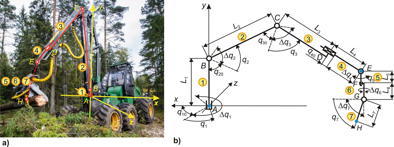
The manipulator kinematic scheme includes its base, three rotary links, and one translational link, providing spatial movement of the harvester head. Each i-th link can make a maximum movement Δqi from the initial position qi0 to the final position qi + Δqi and back. The links form a flat open kinematic chain consisting of four consecutive kinematic pairs of class V (three rotational and one translational). The manipulator has four degrees of freedom, which correspond to angular displacements q1, q2, q3, and the linear displacement q4. The kinematic pair 0-1 is formed by link 0 (base mounted on the harvester supporting frame) and link 1 (manipulator column) with a length of L1. The rotation axis of the cylindrical hinge A is perpendicular to the plane of the supporting frame and coincides with the coordinate axis y. The kinematic pair 1-2 is formed by link 1 and link 2 (boom) with a length of L2. The rotation axis of the cylindrical hinge B is perpendicular to the plane of the kinematic pair and parallel to the coordinate plane x0z. The kinematic pair 2-3 is formed by link 2 and link 3 (handle) with a length of L3. The rotation axis of the cylindrical hinge C is perpendicular to the plane of the kinematic pair and parallel to the coordinate plane x0z. The coordinates of the hinge C are variable and depend on the rotation angles of the kinematic pairs 0-1 and 1-2. The kinematic pair 3-4 is formed by link 3 and a telescoping link 4 of variable length L4. The coordinates of the interface node (point D) are variable and depend on the rotation angles of the kinematic pairs 0-1, 1-2, and 2-3. The coordinates of the end point E are variable and depend on the rotation angles of the kinematic pairs 0-1, 1-2, 2-3, and the linear displacement of the kinematic pair 3-4.
The end point E of the manipulator kinematic scheme coincides with a cylindrical hinge, with which the kinematic schemes of the manipulator and the harvester head are interfaced. The coupling is formed by a kinematic pair 4-5. Link 5 can swing freely; its angular displacement depends on the magnitude and direction of the combined load from the harvester head’s weight and the tree.
The kinematic scheme of the harvester head includes two rotary and one rotational link, which form a flat open kinematic chain of two kinematic pairs of class V. The harvester head has two degrees of freedom, which correspond to angular movements q6, q7. The kinematic pair 5-6 is formed by a link 5 (suspension) of length L5 and a link 6 (fork) of length L6, connected by a cylindrical hinge F. Its rotation axis coincides with the longitudinal axes of the links and is parallel to the coordinate plane x0y. Due to the insignificance of the length L5, it can be assumed that the deviation of the longitudinal axis of the suspension from the vertical during its free swing can be neglected, that is, q5 = 0. The coordinates of the hinge F are variable and depend only on the current displacement values q1, q2, q3, q4. The kinematic pair 6-7 is formed by link 6 (fork) and link 7 (body of the harvester head) of length L7.
Kinematic pairs 0-1, 1-2, 2-3, and 3-4, which make up the manipulator scheme, provide the spatial movement of the end point E of the handle, to which the harvester head is attached. The manipulator provides the required movement of the harvester head to the tree to be cut. Kinematic pairs 5-6 and 6-7, which make up the harvester head kinematic scheme, provide the spatial movement of the hinge G and the point H, which determines the position of the cut plane. This is the orienting movement of the harvester head when performing logging operations, i.e., capturing a tree with the harvester head, sawn it down, transferring the tree after cutting branches into a formed bundle of assortments.
The harvester’s working zone is the space within which the chain saw of the harvester head can be in the working position, that is, the point H with vertical orientation of kinematic pairs 5-6 and 6-7 (Fig. 2). It is spherical and is formed by rotating the section cfhkmc relative to the coordinate axis y by an angle q1.
Fig. 2 - Projections of the harvester’s working zone in the plane x0y (a) and in the plane x0z (b).
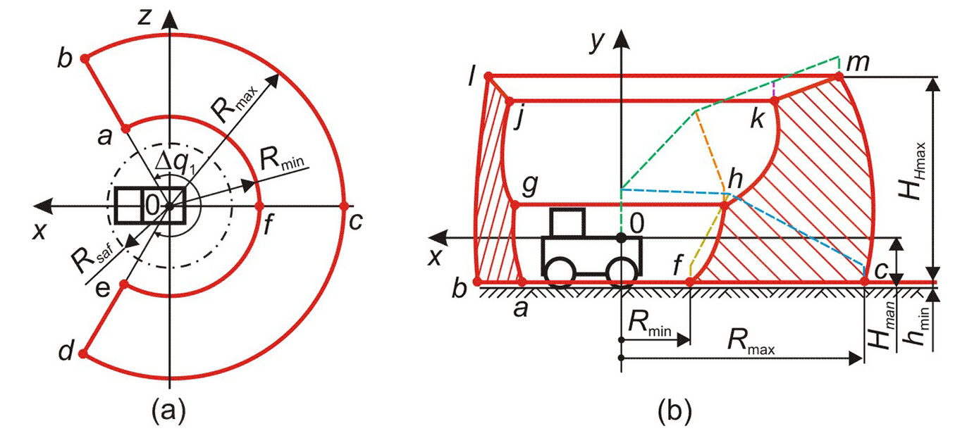
The section cfhkmc is formed by boundary lines - arcs cm, hk, fh and a straight line segment km. Each boundary line ab is formed when one link of the manipulator is moved, and the rest of the links are non-moving. As a consequence, the parametric representation of an arbitrary boundary line ab in the coordinate system xyz can be expressed as (eqn. 1, eqn. 2, eqn. 3):
where ψx is the inclination angle of the ground surface in the x-axis direction, ui is the specified movement of the i-th link, L5-7 = L5 + L6 + L7.
In Tab. 1, for each boundary line, the range of movement of the manipulator link is indicated, which is considered as a moving link when calculating the spatial coordinates of the line using parametric equations eqn. 1, eqn. 2, and eqn. 3. Fixed values of non-moving links movements are also indicated. The displacement q1 is set arbitrarily and allows to build a section cfhkmc in an arbitrary vertical plane in the coordinate system xyz.
Tab. 1 - The specified movements of the manipulator links to determine the position of the boundary lines of the section cfhkmc
| Boundary line | Moving link | Non-moving links |
|---|---|---|
| Arccm | from u2 = 0 (point c) to u2 = Δq2 (point m) | u3 = Δq3 , u4 = Δq4 |
| Archk | from u3 = 0 (point h) to u3 = Δq3 (point k) | u2 = Δq2 , u4 = 0 |
| Arcfh | from u2 = 0 (point f) to u2 = Δq2 (point h) | u3 = 0 , u4 = 0 |
| Segmentkm | from u4 = 0 (point k) to u4 = Δq4 (point m) | u2 = Δq2 ,u3 = Δq3 |
The cross section of the harvester’s working zone with the plane x0z at the level y = -Hman+hmin, which has the shape of an open ring element abcdefa (Fig. 2a), determines the area where the tree to be cut should be located. The dimensions of this area are determined by the limiting rotation angle Δq1 of the manipulator column, the maximum radius Rmax, the minimum radius Rmin, and the area Sw. These characteristics are determined as (eqn. 4, eqn. 5, eqn. 6):
To ensure the safe operation of the manipulator (to avoid touching the metal structure or the harvester cabin with links), the minimum radius Rmin must exceed the radius of safe approach of the harvester head Rsaf. The specified radius can be calculated as (eqn. 7):
where Dh is the transverse dimension of the harvester, Lhh is the longitudinal dimension of the harvester head, ΔRsaf is the additional width of the safety zone.
Optimal mathematic model
The purpose of optimizing the kinematic scheme of the harvester manipulator is to find such a combination of the lengths of its individual links, in which the area Sw, where the tree to be removed is located (ring element abcdefa in Fig. 2a), reaches its maximum value while adhering to several geometric, structural and operational restrictions. Thus, the optimality criterion Kopt is equivalent to the area Sw and is quantified by eqn. 6.
The maximum radius Rmax is achieved when the displacements of the handle and the manipulator telescoping link take the largest possible values q3 = q30+Δq3 and q4 = L4 + q40, and the displacement of the boom is an unknown minimum value q2 = q2,min. The value q2,min must fit the following criterion: in the considered configuration of the manipulator, the characteristic point H, which determines the vertical coordinate of the saw location when cutting down a tree, must lie in the plane of the saw at a height hmin from the ground surface (eqn. 8):
Thus, the desired displacement q2,min is determined by solving the following nonlinear equation (eqn. 9):
Similarly, the minimum radius Rmin is achieved when the displacements of the handle and the telescoping link of the manipulator take the smallest possible values q3 = q30 and q4 = q40, and the displacement of the boom is an unknown maximum value q2 = q2,max. The value q2,max must match the following condition: in the considered configuration of the manipulator, the characteristic point H, which determines the vertical coordinate of the saw location when cutting down a tree, must lie in the plane of the saw at a height hmin from the ground surface (eqn. 10):
Thus, the desired displacement q2,max is determined by solving the following nonlinear equation (eqn. 11):
Among the required parameters to be determined for solving the optimization problem, the link lengths of the manipulator kinematic scheme were included and the vector of the required parameters {x} was formed (eqn. 12):
The remaining parameters used in calculating the optimality criterion Kopt and characterizing the harvester design are fixed parameters.
The task of a four-parameter single-criterion conditional optimization problem of the manipulator kinematic scheme is formulated as follows: it is required to find such a combination of required parameters {x}opt with values of fixed parameters set as initial data, at which the maximum optimality criterion Kopt is achieved, taking into account the necessary design and regime restrictions. Mathematically, the optimization problem is characterized by a set of the following computational equations (eqn. 13 to eqn. 20); (i) objective function:
and (ii) restrictions in the form of inequalities, according to the condition of a non-negative value of geometric dimensions and link displacements (eqn. 14):
[i = 1, 2, 3, 4], and according to the condition that the geometric dimensions and link displacements do not exceed the specified limit values (eqn. 15 to eqn. 18):
To ensure the stability of the harvester against overturning due to tipping moments created during operation, it is essential to consider the weight loads from the metal structure of the links, the harvester head, and the sawn tree (eqn. 19):
To ensure the required size of the safe approach zone for the harvester head relative to the harvester’s metal structures, we define (eqn. 20):
where L1,min, L1,max are the minimum and maximum permissible length of the manipulator column, k34 is the coefficient of relative length of the telescoping link, [Mt] is the load moment of the harvester manipulator, Mt,max is the maximum tipping moment during harvester operation.
The developed optimal mathematical model was implemented using the software “Optimization_of_ Harvester_Manipulator” ([17]). To find the optimal combination of the link lengths of the manipulator kinematic scheme, the method of conditional multidimensional single-criteria optimization of the Hook-Jeeves type ([28]) was used. Previous experience in solving optimization problems showed that objective functions have a complex topology, and therefore, they can have several different extremes ([1], [15]). To eliminate the erroneous finding of the desired vector {x}opt, an algorithm was used for iterating through the initial optimization points. This algorithm provides the identification of all local extrema of the objective function within the range of its acceptable values, and the determination of the true global extreme, which is the vector {x}opt. The algorithm allows for adjusting the lengths of links Li by increments ΔLi within specific intervals of permissible change Li,min< Li< Li,max. Test calculations showed that recommended values for these steps ΔLi are approximately 0.2 m. The problem is solved when hen the possible combination of lengths satisfies the restrictions of eqn. 14 to eqn. 20, and the local extreme point of the objective function (eqn. 13) is determined. As a result, a set of local extremes is achieves, and the extreme with the maximum value of the objective function is selected among them.
The result of the software is the optimal combination of the lengths of individual links in a harvester manipulator with four degrees of freedom. This includes three rotary links and one telescopic link. These manipulators are currently the most commonly used in modern harvester designs ([32], [34]). In addition to the components of the desired vector {x}opt, the algorithm calculates the key geometric characteristics of the optimal harvester working zone where the tree to be cut should be located. These include the minimum and maximum radii, square, volume, and maximum height of the chainsaw above the ground surface. Such information is essential at the initial stage of designing a manipulator, as it allows the designer to predict its functionality by considering the technical specifications of the harvester.
An important characteristic of the harvester, which determines its functionality, is the manipulator load moment [Mt]. It determines the maximum dimensions of the trees (diameter dtr,max, length ltr,max, and weight Gtr,max of the assortments) that the harvester can cut down and stack into a formed bundle. For modern harvesters ([5]), the magnitude of the load moment is up to 300 kN m or more. Optimization calculations were performed in the range from 150 kN m to 300 kN m. The harvester Amkodor 2561 (Fig. 1a) served as the basis for initial structure for test calculations and further analysis. Its main technical characteristics are: transverse dimension Dh = 2.6 m, height of the manipulator installation Hman = 1 m, manipulator load moment [Mt] = 225 kN·m, weight and longitudinal dimension of the harvester head Ghh = 10 kN and Lhh = 1.4 m.
Results and discussion
The results showed that the objective function O({x}) does not provide a smooth surface within the four-dimensional domain defined by the constraints described in eqn. 14 to eqn. 20. Indeed, it has a complex topology with several local maxima that correspond to various optimal combinations of manipulator link lengths {x}opt. As a rule, within the scope of determining possible solutions, the objective function can have from 10 to 15 local maxima, depending on the combination of initial data. Obviously, only one of these maxima is the best solution to the optimization problem (i.e., it is a global maximum). The variation in the value of Sw corresponding to the local maxima reached a noticeable value of up to 30%. However, some of the local maxima took values that are quite similar, differing only by up to 2%, and in some cases they were nearly equal to the objective function value at the global maximum. Therefore, when designing a harvester, it is advisable to take into account such local maxima, as additional requirements (e.g., constructive, technological, operational, economic or environmental reasons) may prevent the use of the global maximum of the objective function.
Our results indicate that optimizing the combination of link lengths of the manipulator’s kinematic schemes can increase the area Sw of the harvester’s working zone by up to 30%, i.e., the area within which the harvester can effectively cut down trees during one stop. The increase in square is correlated with an increase in the maximum radius Rmax of the working zone. The corresponding increase in the maximum radius ranged from 15% to 17%. These results were obtained based on the technical specifications of the Amkodor 2561 harvester, which was used as a test case. Obviously, different technical specifications of the harvester will provide different quantitative values compared to the Amkodor 2561, but we can assume that the general trend will likely remain consistent with our findings.
The increase in the area Sw of the harvester’s working zone entails a similar increase in the width of the strip of felled trees at eachpass of the harvester, as well as an increase in the distance between two adjacent technological stops of the harvester through the logging area. Reducing the number of longitudinal passes and the number of stops within the the logging area reduces the negative impact of mechanized logging on the forest ecosystems ([11], [10]).
Fig. 3 - The influence of the load moment and the tree weight on the shape and size of the harvester’s working zone. (a) [Mt]=150 kN m; (b) [Mt]=225 kN m; (c) [Mt]=300 kN m; (1): Gtr=8 kN; (2) Gtr=7 kN; (3): Gtr=6 kN; (4): Gtr=5 kN; (5): Gtr=4 kN.
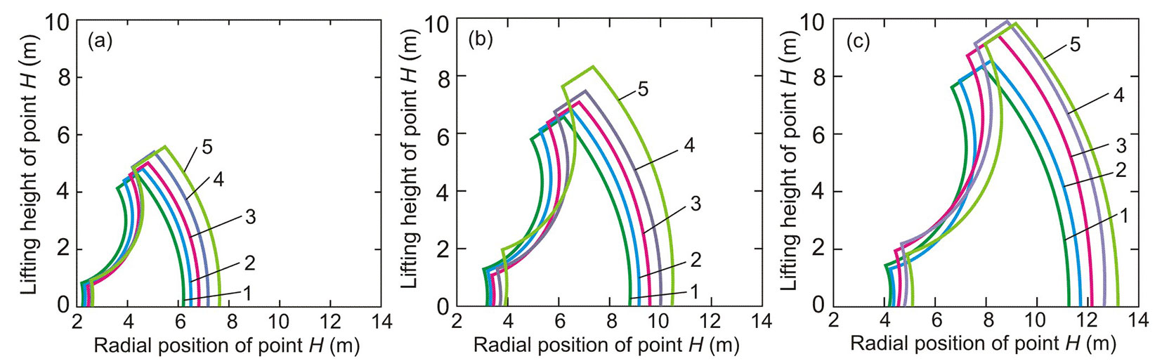
Fig. 3shows the vertical sections of the harvester’s working zone with different load moment (e.g., assortments of different weights). The geometric extension of the working zone decrease with decreasing the load moment and increasing the assortment weight. This leads to a reduction in the optimized area Sw. The optimization was performed for a tree of the maximum possible weight that the harvester should handle, i.e., for a tree with the maximum average trunk diameter (eqn. 21):
where ρtr is the tree density. Wood density varies widely depending on tree species and environmental conditions ([31]). Therefore, the diameter of the thickest trees that a harvester can cut down (i.e., the maximum load moment) is not a constant value and varies for different logging areas. Thus, the choice of the most effective harvester size in a particular logging area should take into account the type and maximum diameter of trees of the logging area and the required assortment length.
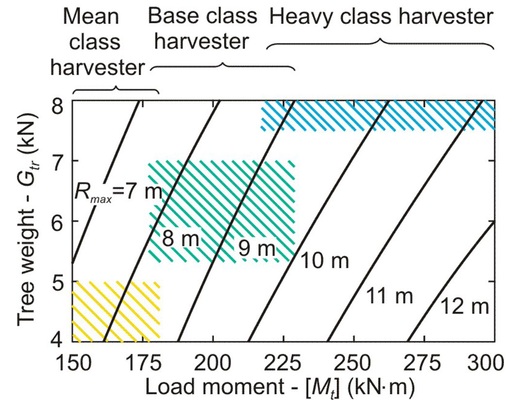
Fig. 4shows the combined effect of the load moment and the tree weight on the area Sw (Fig. 4a) and the maximum radius Rmax (Fig. 4b) of the optimal harvester’s working zone. Function Sw([Mt], Gtr) is graphically expressed by a linear surface, and function Rmax([Mt], Gtr) is expressed by a weakly convex (almost linear) surface. Depending on the magnitude of the load moment, modern harvesters are arbitrarily divided into separate size classes. According to the classification by Syunev et al. ([32]), light class harvesters have a load moment of less than 120 kN·m, medium class harvesters up to 180 kN·m, base class harvester up to 220 kN m, and heavy class harvesters with a load moment > 220 kN m. Fig. 5shows the isolines of maximum radii within the space of the studied parameters {[Mt] - Gtr} and indicates the recommended areas of assignment of these parameters for optimal design of manipulators for harvesters of various classes. As the tree weight decreases, the maximum radius of the optimal harvester’s working zone increases. Therefore, optimizing the kinematic scheme of the manipulator has a significant effect when operating harvesters in logging areas with trees of a smaller average diameter.
Fig. 4 - The influence of the load moment and the tree weight on the geometric characteristics of the harvester’s working zone. (a) Area Sw ; (b) maximum radius Rmax.
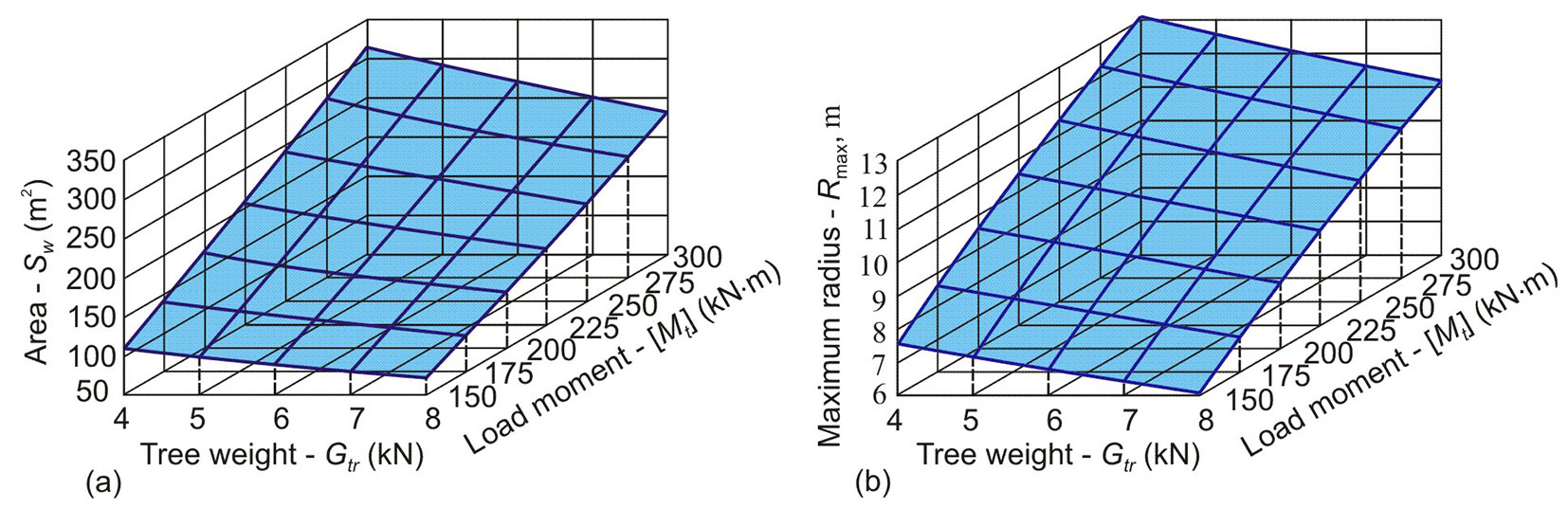
Fig. 5 - Isolines for Rmax= const in the parameter space {[Mt] - Gtr}.
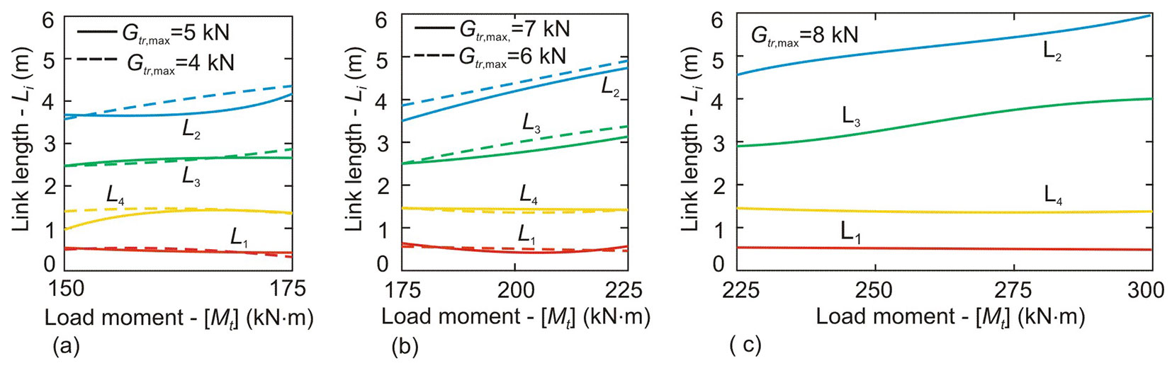
The optimal lengths of the manipulator links for harvesters of different classes, depending on the values of parameters [Mt] and Gtr,max accepted in the design, are shown in Fig. 6. The lengths of the column and the telescoping link are independent on the design parameters. As the load moment of the harvester increases, the size of the working zone also expands due to the simultaneous increase in the lengths of the boom and the handle, with typically exceeds about 1.5 to 2.0 m.
Fig. 6 - Optimal lengths of manipulator links for harvesters of various classes. (a) Mean class harvester; (b) base class harvester; (c) heavy class harvester.
Conclusion
Based on our results, optimizing the working equipment for forest machines and, in particular, the design of harvester manipulators for cutting trees, can effectively increase their technical, operational, and economic characteristics, and significantly reduce the negative impact on forest soil. An effective approach to minimize the impact of harvesters in the forest is to create kinematic schemes for manipulators aimed to maximize their working zone during operations. To this purpose, we developed a mathematical model and a specific software that were used for optimizing the working zone of the manipulator of the Amkodor 2561 harvester. The model can be applied to other types of harvesters equipped with similar manipulators based on four-link articulated kinematic schemes.
Our results showed that, considering harvesters with a load moment ranging from 150 to 300 kN·m, the area of the harvester’s working zone (i.e., the area within which the harvester can cut trees during one stop) can increase up to 30% using an optimal combination of link lengths in the kinematic scheme of the manipulators. This is due to an increase in the maximum radius of the working zone, which can range from 15% to 17%. As a result, the width of the felled tree strip at one pass and the distance between adjacent harvester stops increase, thereby reducing the number of longitudinal passes and harvester stops, and ultimately the negative impact of mechanized logging on the forest.
Further increases in the size of the working zone can be achieved using harvesters with a large load moment. However, this can cause an increase in their weight and can lead to a nonlinear increase in the deformation of forest soils, thus increasing the duration of ecosystem restoration after logging. Therefore, a promising direction for further research is the development of measures to reduce the own weight of the manipulator links based on optimizing their design and the use of modern materials with increased strength-to-weight ratio.
Acknowledgements
AL proposed the research topic and completed the preparation of the manuscript final version; AL, IL, AM participated in the development of a mathematical model and evaluation of its correctness; IL developed and tested the software; AM performed calculations and analyzed their results. All authors read and approved the final manuscript.
References
Gscholar
Gscholar
Gscholar
Gscholar
Gscholar
Gscholar
Gscholar
Authors’ Info
Authors’ Affiliation
Faculty of Technology and Design, Academician IG Petrovskii Bryansk State University, Bryansk, 241036 (Russia)
Rectorat, Kuban State Technological University, Krasnodar, 350072 (Russia)
Faculty of Physics and Mathematics, Academician IG Petrovskii Bryansk State University, Bryansk, 241036 (Russia)
Corresponding author
Paper Info
Citation
Lagerev A, Lagerev I, Makulina A (2025). Improving the harvester functionality by optimizing the manipulator kinematic scheme. iForest 18: 227-233. - doi: 10.3832/ifor4753-018
Academic Editor
Rodolfo Picchio
Paper history
Received: Nov 05, 2024
Accepted: Aug 05, 2025
First online: Aug 26, 2025
Publication Date: Aug 31, 2025
Publication Time: 0.70 months
Copyright Information
© SISEF - The Italian Society of Silviculture and Forest Ecology 2025
Open Access
This article is distributed under the terms of the Creative Commons Attribution-Non Commercial 4.0 International (https://creativecommons.org/licenses/by-nc/4.0/), which permits unrestricted use, distribution, and reproduction in any medium, provided you give appropriate credit to the original author(s) and the source, provide a link to the Creative Commons license, and indicate if changes were made.

Web Metrics
Breakdown by View Type
Article Usage
Total Article Views: 4833
(from publication date up to now)
Breakdown by View Type
HTML Page Views: 1783
Abstract Page Views: 1493
PDF Downloads: 1328
Citation/Reference Downloads: 3
XML Downloads: 226
Web Metrics
Days since publication: 320
Overall contacts: 4833
Avg. contacts per week: 105.72
Article Citations
Article citations are based on data periodically collected from the Clarivate Web of Science web site
(last update: Mar 2025)
(No citations were found up to date. Please come back later)
Publication Metrics
by Dimensions ©
Articles citing this article
List of the papers citing this article based on CrossRef Cited-by.
Related Contents
iForest Similar Articles
Research Articles
Fine root production and distribution in the tropical rainforests of south-western Cameroon: effects of soil type and selective logging
vol. 3, pp. 130-136 (online: 27 September 2010)
Research Articles
Variation of wood and bark density and production in coppiced Eucalyptus globulus trees in a second rotation
vol. 9, pp. 270-275 (online: 08 September 2015)
Review Papers
Pathways to increase supply of sustainable wood from planted forests and trees to address bioeconomy needs: a review
vol. 19, pp. 168-185 (online: 12 May 2026)
Research Articles
Optimizing silviculture in mixed uneven-aged forests to increase the recruitment of browse-sensitive tree species without intervening in ungulate population
vol. 11, pp. 227-236 (online: 12 March 2018)
Research Articles
Heuristic forest planning model for optimizing timber production and carbon sequestration in teak plantations
vol. 10, pp. 430-439 (online: 24 March 2017)
Technical Reports
Diversity pattern of vegetation in and around proposed Kotlibhel hydroelectric project along the Alaknanda River in Garhwal Himalaya (India)
vol. 4, pp. 38-43 (online: 27 January 2011)
Research Articles
Impact of rotation length of Eucalyptus globulus Labill. on wood production, kraft pulping, and forest value
vol. 15, pp. 433-443 (online: 20 October 2022)
Research Articles
Interaction between planting spacing and wood properties of Eucalyptus clones grown in short rotation
vol. 14, pp. 12-17 (online: 02 January 2021)
Review Papers
Towards better practices of salvage logging for reducing the ecosystem impacts in Mediterranean burned forests
vol. 13, pp. 360-368 (online: 25 August 2020)
Research Articles
Wood production and nutritional status of Pinus taeda L. in response to fertilization and liming: a meta-analysis of the Americas
vol. 16, pp. 195-201 (online: 25 July 2023)
iForest Database Search
Search By Author
Search By Keyword
Google Scholar Search
Citing Articles
Search By Author
Search By Keywords
PubMed Search
Search By Author
Search By Keyword